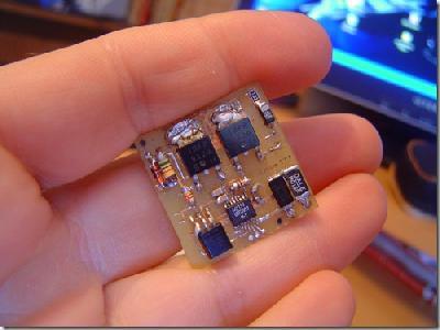
How to make a 12v to 5v Regulator

So let’s say you have this digital camera that can take pictures and videos as well, cool eh? But there’s a catch, its battery drains electricity charge fast. The solution, use an external battery, but the hassle of using external batteries is that most of the batteries are 12 volts. So you have to reduce the power voltage as your device gains charge from the higher voltage battery.

12v to USB adapter 12v to 5v transformer

This project is also helpful in cars. We can use a USB adapter and convert a 12 volt to a 5 volt transformer. This are great when you charge devices that only requires a little let say like 5 volts digital cameras, cellular phones and tablets. If you need 5 volts for anything other than USB, simply skip the steps about adding the USB ports.

Here are the things that you will need:

  • a fuse holder
  • a 0.5 amp fast blowing fuse (you can use a higher rated one if you use a different transistor that can take higher amperage. Because we put the fuse on the 12v side, (which can vary from 11.5-12.5 volts, we have to use a value 2.5x smaller than what we want on our USB side. So, if you want 1.5 amps for your USB ports, then you select a 0.6amp fuse, if you want 2.5 amps at 5v, you select a 1 amp fuse, if you want 3.75 amps, you select a 1.5 amp fuse, etc.)
  • 2 different colors of wire (so that you don’t get confused later on)
  • a L7805CV voltage regulator, part number 497-1443-5-ND from Digikey (search for 296-11414-5-ND if you want higher AMP output, like 2 amps since it is a max of 3 amps along with a 1-1.2 amp fast blowing fuse, and LT1084CT-5#PBF-ND if you want 2 ports at 2 amps each, along with a 1.5-1.75 amp fast blowing fuse.)
  • a 220uf 16v Capacitor, part number P5139-ND from Digikey.
  • female USB ports times the number of ports you want (2-3 would be normal, you can expect most devices to use up to 0.5A each, except for tablets that can use 1-2 amps), Digikey number AE9923-ND
  • if you choose to add an LED, you need an LED and an appropriate resistor for 5V. This depends on your LED’s rating. Any LED will do, here are the values for the most common LEDs : 1.2v = 220ohm, 1.6v = 180ohm, 2v = 180 ohm, 2.2v = 150ohm. If you have a strange LED or want to make it brighter, please use this resistor calculator.

Conclusion

It is always helpful when you have a simple 12v to 5v converter, when you are on the road for a little vacation, charging small devices as never been so easy.

Check out the original post

DC – DC Buck Converter

SMPS-basic-2

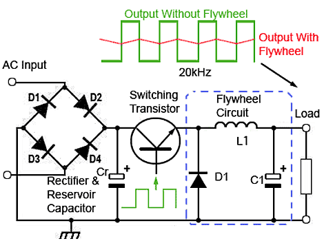
A buck converter is a voltage step down and current step up converter. It is used in SMPS circuits where the DC output voltage needs to be lower than the DC input voltage. The DC input can be derived from rectified AC or from any DC supply. It is useful where electrical isolation is not needed between the switching circuit and the output, but where the input is from a rectified AC source, isolation between the AC source and the rectifier could be provided by a mains isolating transformer.

The basic operation of the buck converter has the current in an inductor controlled by two switches. All the components are considered to be perfect in the idealized converter. The switch and the diode have zero voltage drop when on and zero current flow when off and the inductor has zero series resistance. Further, it is assumed that the input and output voltages do not change over the course of a cycle.

The switching transistor between the input and output of the Buck Converter continually switches on and off at high frequency. The circuit uses the energy stored in the inductor to maintain a continuous output, during the on periods of the switching transistor, to continue supplying the load during the off periods. The circuit operation depends on what is sometimes also called a Flywheel Circuit. This is because the circuit acts rather like a mechanical flywheel that, given regularly spaced pulses of energy keeps spinning smoothly at a steady rate.

Here’s the full article.

How to repair/troubleshoot your SMPS?

A switched-mode power supply or SMPS or sometimes called the switcher, is an electronic power supply that incorporates a switching regulator to convert electrical power efficiently. An SMPS transfers power from a source, like any other power supplies, like mains power, to a load, such as a personal computer, while converting voltage and current characteristics.

So what if your SMPS got broke? With a little electronics know-how and some guides, it should be simple. Knowledge is power. Don’t forget that the SMPS repairing guide is packed with invaluable step-by-step instructions presented by a reputable and highly experienced electronics engineer.

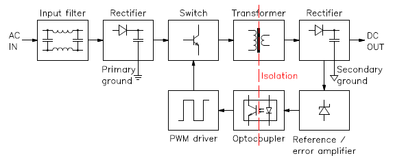
Some say that it’s extremely difficult to repair a switch more power supply. No! It’s not. The first thing to do is to take a closer look at the SMPS structure. It would be best to look at the generic block diagram of a SMPS. The image below is a simple structure.

smps-structure

Safety is our primary concert.

SMPS are dangerous circuits, so before starting to troubleshoot, safety should come first. Just reminders, half of the components are directly connected to the mains voltage, so voltage shock would be painful. A large storage capacitor is charged at high voltage and can be dangerous even when the mains supply is disconnected. The capacitors could stay charged for a long time since not all SMPS include bleeding resistors or even some might be broken. If you don’t know exactly what you’re doing, might as well call an experienced technician.

It’s good to do a visual inspection

smps-fuse-small

It is always good to do a visual inspection. First, disconnect the SMPS and make sure all capacitor are discharged. Burned resistor can be spotted by their black colour and bad smell. It is important to always check the ferrite transformer, if it looks burned and smells badly, we can give it up because it may sometime have shorted turns and it will be a nightmare to repair or find a replacement part. If the transformer if faulty, it would be best to replace the whole SMPS and will save us a lot of time.

No output, good fuse

SMPS can fail in many different ways, but the most common would be no output power at all. With this, start by checking the input fuse. If the fuse is good but there is no output, probably all the semiconductors are good and it could be easy to fix.

No output, blown fuse

If the fuse is open, then something went really wrong in the circuit. Although don’t replace the fuse yet, as it would just blow again; you have to fix first a short circuit somewhere. Typical problems are blown up power transistors or rectifier diodes, especially on the primary side.

SMPS partially working

ext-dc-source-trick-small

There are times when the SMPS is only partially working; it may start for a fraction of a second then shuts down or it may pulsate trying to start every few seconds and shutting down after a fraction of second, or it may producing a wrong output voltage. Probably all power semiconductors are good, so the first thing to check are the capacitors.

Check the capacitors

Often the cause of SMPS problems is the electrolytic capacitors. In what we call cheap designs, where thermal dissipation is a bit too close to the limit, and a choice of components a bit too cost-oriented, electrolytic capacitors are oftentimes real time-bombs that will eventually fail or sometimes explodes. The liquid electrolyte inside these components tends to evaporate and dry out completely altering the characteristics.

Here’s the full article.

How Do Voltage Regulators Work?

Linear and switching are the two types of voltage regulators. It generates a fixed output voltage of a preset magnitude that remains constant despite everything on the changes to its load conditions or input voltage.

An active (BJT or MOSFET) pass device is employed by a linear regulator which is controlled by a high gain differential amplifier. A precise reference voltage and the output voltage are compared by the linear regulator. To maintain a constant output voltage, it adjusts the pass device.

Switching regulator on the other hand converts dc input voltage to a switch voltage applied to a power MOSFET or BJT switch. To keep the output remains constant regardless of input voltage or load current changes, the filtered power switch output voltage is fed back to a circuit that controls the power switch on and off times.

block_PMP_ADP1612_13_

What are some of the switching regulator topologies?

The three common topologies are: buck (step-down), boost (step-up) and buck-boost (step-up/step-down). Some other topologies include the flyback, SEPIC, Cuk, push-all, forward, full-bridge and half-bridge topologies.

How does switching frequency impact regulator designs?

Higher switching frequencies mean the voltage regulator can use smaller inductors and capacitors. It also means higher switching losses and greater noise in the circuit. What losses occur with the switching regulator? Losses occur as a result of the power needed to turn the MOSFET on and off, which are associated with the MOSFET’s gate driver. Also, MOSFET power losses occur because it takes a finite time to switch to/from the conduction to nonconduction states. Losses are also due to the energy needed to charge and discharge the capacitance of the MOSFET gate between the threshold voltage and gate voltage.

View the original article here.

What is a DC-DC converter?

Think of a DC-to-DC converter as an elevator. The elevator takes a person from one floor to another. Like an elevator, the DC-to-DC converter converts a source of direct current (DC) from one voltage to another level. It’s a class of power converter.

DC_DC_Converter_Circuit_Diagram

We can see this kind of electronic circuits and are important on portable electronic devices such as cellular phones and laptop computers, which are supplied primarily with power from batteries. This kind of devices often contain several sub-circuits, each with its own voltage level requirement different from that supplied by the battery or an external supply or sometimes higher or lower that the supply voltage. Additionally, the battery voltage declines as its stored energy is drained. Switched DC to DC converters offer a method to increase voltage from a partially lowered battery voltage thereby saving space instead of using multiple batteries to accomplish the same thing.

There are also other examples converters that are used on railway or transit applications. Such converters are important to provide the ultra-wide input range, robust filtering, rugged packaging and high reliability required for railway/transit applications.

The output voltage is regulated in most DC to DC converters. But there are some exceptions which include high-efficiency LED power sources, which are a kind of DC to DC converters that regulates the current through the LEDs, and simple charge pumps which double or triple the output voltage.

DC to DC converters developed to maximize the energy harvest for photovoltaic systems and for wind turbines are called power optimizers.

That LED Lamp is Awesome for Christmas!

simbang gabi

More of my post, the coming weeks well be all about Christmas. Who doesn’t like Christmas eh? It’s the time of the year where you receive present and lots of food. What I love about Christmas is the Filipino tradition of “Simbang Gabi”. We would wake up early dawn, around 3 o’clock so we can attend the mass. There are going to be lots of lights on the streets. And on the church, it will be full of decorations, Christmas lights and the Nativity scene; it’s one of my favorite parts in the church on Christmas season.

So as I was checking all the decorations and lightings of the church, I was so interested in this one lamp. I was thinking that it was not an ordinary lamp because it stands out with the rest of the lighting. It turns out, the lamp was custom made. I was so eager to know how it was made since I want to have that lamp as decoration in my house this Christmas. I found this guide while searching the web. It’s a guide on how to create an ultra bright LED lamp from scratch. With a little electronics knowledge, I’ll be able to get my hands dirty on this and have some awesome lamp.

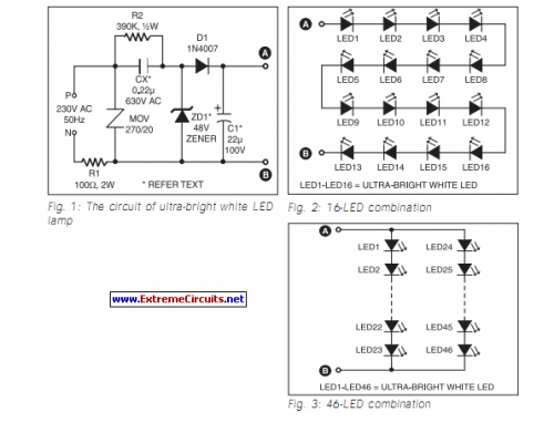
Ultra Bright LED Lamp

The ultra-bright while LED lamp works on 230V AC with minimal power consumption. It can be used to illuminate VU meters, SWR meters, etc. These LEDs emit a 1000-6000mCd bright white light like welding arc and work on 3 volts, 10 mA. Their maximum voltage is 3.6 volts and the current is 25 mA. Anti-static precautions should be taken when handling the LEDs.

It’s Christmas! Time to Decorate our House!

I’ve been out for a couple of weeks and haven’t really visited the Internet, which means no blogging for me. It’s December 1, it’s Christmas season again! I’m pretty excited because this time of the year, we get to decorate the entire house! Lots of Santas and Elves coming our way!

Santa_Claus

We will decorate the house with some old and new decors. My wife bought these lights for our Christmas trees. We will also be decorating the house with mistletoes, poinsettias and ribbon decorations. These are all my wife’s ideas.

Exterior Christmas Lights

As for me, I am preparing something for our Christmas decoration. I’ve this guide about Christmas LED displays that shows various images, a perfect fit for a unique Christmas décor. The projects will be an 8×16 pixel array built with ATtiny861 microcontroller which can show images, like Santa images or even candles, it will be displayed in a window to provide eye catching displays to passersby.

Christmas LED Display for Various Images

The main component of the hardware is the ATtiny861 microcontroller which runs at 20MHz. In order for the microcontroller to dim the LEDs without any visible flickering, the speed should be fast enough. A vertical row of 16 LEDs are driven by each of the eight A6276 driver ICs from Allegro Microsystems. Since there is no internal regulator needed on the circuit board, a regulated 5V wall pack can be used to run the board.

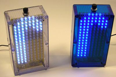
A total of 128 LEDs is contained in the circuit which results to building up 3 boards. The mixture of blue and white LEDs are in the first board, all blue LEDs in the second board, and all white LEDs were built up in the third board. The white LED board went into a transparent enclosure while the blue LED board went into a semi-transparent blue enclosure. Near the center of the board is the huge block of DIP ICs which serve as the driver chips for LEDs.

I want to Save My Laptop Battery From Total Destruction

Laptops are considered one of the most portable devices you can carry. Laptops have evolved from a luxury device in the past and then became a common device in the present. I think many, while not all can afford a laptop these days. It became cheap because of the competition, not just cheap, but the coming of tablets made the laptops more affordable.

How to Repair Laptop Battery

One disadvantage of owning a laptop is its battery lifespan. Laptops batteries are one of the many parts a laptop are having trouble, if can be frustrating at times. When you’re not careful, your battery lifespan might get shorter, every day when you are over-charging it. Laptop batteries are too expensive when replaced. So here’s a guide I found in how to salvage your laptop batteries.

It must be remembered that most laptop batteries cannot be repaired if damaged. This is because of their complex construction. And even if it were to be repaired, one would need specific and expensive instruments to do so.

The battery has two parts, the chemical and the digital circuit. Chemical part can be restored with the risk of getting your files would be corrupted. It should be checked regularly for compatibility every time you use existing chargers. Batteries must also be kept alive with enough supply of voltage during cell replacements. Disconnecting the circuit, if only for a fraction of a second, can erase vital data and render the circuit unusable. To assure continued operation when changing the cells, connect a secondary voltage through a 100 Ohm resistor before disconnecting the cells. Always keep in mind to remove the secondary supply only after the circuit is fed with the needed operating voltage from the new cells.

Here’s a full description of the project.

The Good Ol’ Atari Joysticks

The Atari game console has its glorious times back in the days. The Atari game console was at the peak on the golden age of arcade video games. The Atari helped define the electronic entertainment industry from the 1970s to the mid-1980s.

atari4

Atari will always have a special place in my heart. I had a wonderful childhood because of this invention. I played long hours playing the games Missile Command. I also spent so much time playing Pole Position, being an F1 driver, at least on the video game.

Back to the present, I have this one interesting project in mind. My son always plays computer games, but not like the ones I used to play in the past. Today is the age of PC gaming, Atari have gone, not gone totally, but this era is for PC gaming. I wanted for my some to experience what I played, so I wanted to build this Atari joystick for his PC gaming.

The Atari joystick will be connected though the USB port. What I wanted to do is emulate Atari games on his PC. There are a lot of Atari emulators out there that’s free.

PC Gaming with Atari Joystick through USB Adapter

A cheap USB gamepad can be used in this project especially those without pressure sensitive buttons or analog joysticks but only digital inputs. This will avoid paying for unwanted parts for the adapter. The plastic casing of the Logitech Wingman Precision USB gamepad was removed and concentrated on the internals. The tracing of connections from input to the pins of the single IC was made easy because the layout of the circuit board is really sparse.

To power auto-fire circuits, most computers that have Atari joystick ports provide +5V on the pin 7 of the D-sub connector. The auto-fire function present in some joysticks can also be activated by connecting the D-sub pin 7 with the pin 10 on the IC with a safety resistor. A second fire button can also be produced by connecting the D-sub connector pin to pin 4 (Button 2) on the Logitech chip. The effective way is soldering the wires of the 9-pin D-sub connector into the pins required by the joystick and the other ends straight to the pins of the Logitech chip.

The board and the connector were installed in a small plastic box to make the adapter ready. It can be made smaller if the IC and other parts were unsoldered and placed on veroboard.

The Walls have Ears

Remember how I wrote an article about me creating a spy microphone, well, on this article we will be discussing about Spy Ears. The DIY spy microphone was cool, but the setup will be cooler and awesome if we add this spy ears. Imagine you can hear anything from a long distance. You can hear conversations from another room or beyond the wall.

walls-have-ears

While binoculars improve vision, this personal sound enhancer circuit improves listening. This gadget will have a light weight; it will produce an adjustable gain on sounds that is picked up from a built-in high-sensitivity microphone.

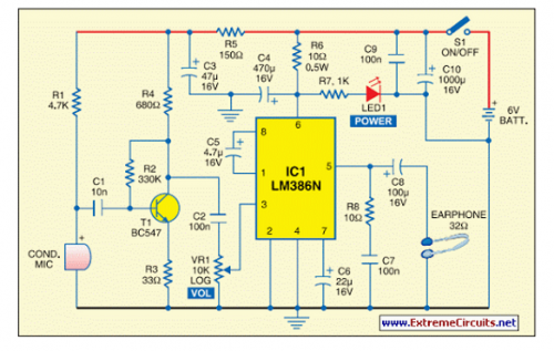
Here’s the circuit diagram for the original article:

Spy Ear Circuit Diagram

As shown in diagram above, a small signal amplifier is built around transistor BC547 (T1).

Transistor T1 and the related components amplify the sound signals picked up by the condenser microphone (MIC). The amplified signal from the preamplifier stage is fed to input pin 3 of IC LM386N (IC1) through capacitor C2 (100nF) and volume control VR1 (10-kilo-ohm log). A decoupling network comprising resistor R5 and capacitor C3 provides the preamplifier block with a clean supply voltage. Audio amplifier IC LM386N (IC1) is designed for operation with power supplies in the 4-15V DC range.

It is housed in a standard 8-pin DIL package, consumes very small quiescent current and is ideal for bat tery-powered portable applications. The processed output signal from capacitor C2 goes to one end of volume control VR1. The wiper is taken to pin 3 of LM386N audio output amplifier. Note that the R6-C4 network is used to RF-decouple positive-supply pin 6 and R8-C7 is an optional Zobel network that ensures high frequency stability when feeding an inductive headphone load.

Capacitor C6 (22µF, 16V) wired between pin 7 and ground gives additional ripple rejection. The output of LM386N power amplifier can safely drive a standard 32-ohm monophonic headphone/earphone. Assemble the circuit on a small general-purpose PCB and house in a suitable metallic enclosure with an integrated battery holder and headphone/earphone socket. Fit the on/off switch (S1), volume control (VR1) and power indicator (LED1) on the enclosure. Finally, fit the condenser microphone (MIC) on the front side of the enclosure and link it to the input of the preamplifier via a short length of the shielded wire.

Good thing I found this Spy Ear guide, it’s really a cool project to build for your spy role.

Blog at WordPress.com.

Up ↑